
PC(Program Counter)
8bit Register
↓ Code & Schematic
reg8.v
'timescale 1ns / 1ps

module reg8(
    input [7:0] data_in,
    input inen,
    input oen,
    input clk,
    input clr,
    output [7:0] data_out
    );

    reg [7:0] st;

    always @ (posedge clk or posedge clr) begin
        if (clr)
            st <= 8'b0;
        else if (inen)
            st <= data_in;
        else
            st <= st;
    end
    assign data_out = (oen) ? st : 8'bz;
endmodule
tb_reg8.v
'timescale 1ns / 1ps

module tb_reg8();

reg [7:0] data_in;
reg inen;
reg oen;
reg clk;
reg clr;

wire [7:0] data_out;

reg8 UUT (
.data_in(data_in),
.data_out(data_out),
.inen(inen),
.oen(oen),
.clk(clk),
.clr(clr)
);

always #50 clk=~clk;
initial begin
data_in = 8'h48;
inen = 0;
oen = 0;
clk = 0;
clr = 1;
#100; clr = 0;
#200; inen = 1;
#100; oen = 1;
#100; oen = 0;
#100; inen = 0; oen = 1;
#100; clr = 1;
#100; clr = 0;
#100;
end
endmodule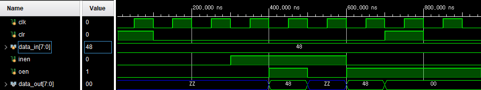
Half Adder
↓ Code
ha.v
'timescale 1ns / 1ps

module ha(
    input x,
    input y,
    output s,
    output c
    );

    assign s = x ^ y; // sum
    assign c = x & y;// carry out
endmodule
ha8.v
'timescale 1ns / 1ps

module ha8(
    input [7:0] data_in,
    input pc_inc,
    output [7:0] data_out
    );

    wire a [7:0] ;
    genvar i;

    generate
        ha ha0( pc_inc, data_in[0], data_out[0], a[0]);
        for(i = 1; i < 8; i = i + 1) begin : hagen
            ha ha1(a[i-1], data_in[i], data_out[i], a[i]);
        end
    endgenerate
endmodule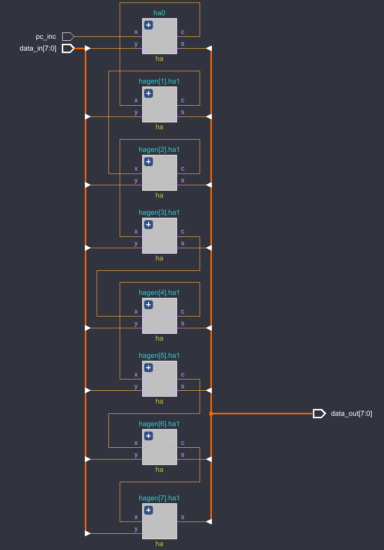
PC(Program Counter)
↓ Code
pc.v
'timescale 1ns / 1ps
module pc(
    input clk,
    input clr,
    input pc_inc,
    input load_pc,
    input pc_oen,
    input [7:0] pc_input,
    output [7:0] pc_out
    );

    wire [7:0] a;
    wire [7:0] b;
    wire [7:0] c;

    ha8 u0(
    .data_in    (a),
    .data_out  (b),
    .pc_inc       (pc_inc)
    );
    assign c = (load_pc) ? pc_input : b;

    reg8 u1(
    .data_out    (a),
    .data_in       (c),
    .inen             (1'b1),
    .oen               (1'b1),
    .clk                 (clk),
    .clr                  (clr)
    );
    assign pc_out = (pc_oen) ? a : 8'bz;
endmodule
tb_pc.v
'timescale 1ns / 1ps

module tb_pc();

    reg pc_oen;
    reg pc_inc;
    reg load_pc;
    reg [7:0] pc_input;
    reg clr;
    reg clk;

    wire [7:0] pc_out;

    pc uut(
    .pc_out(pc_out),
    .pc_oen(pc_oen),
    .pc_inc(pc_inc),
    .load_pc(load_pc),
    .pc_input(pc_input),
    .clr(clr),
    .clk(clk)
    );

    always #50 clk = ~clk;
    initial begin
        pc_oen = 1;
        pc_inc = 0;
        load_pc = 0;
        pc_input = 8'h13;
        clr = 1;
        clk = 0;
        #100; clr = 0;
        #100; pc_inc = 1;
        #500; pc_inc = 0;
        #100; load_pc = 1;
        #100; load_pc = 0;
        #400; pc_oen = 0;
        #100; pc_oen = 1;
        #100; clr = 1;
        #100; clr = 0;
        #100;
    end
endmodule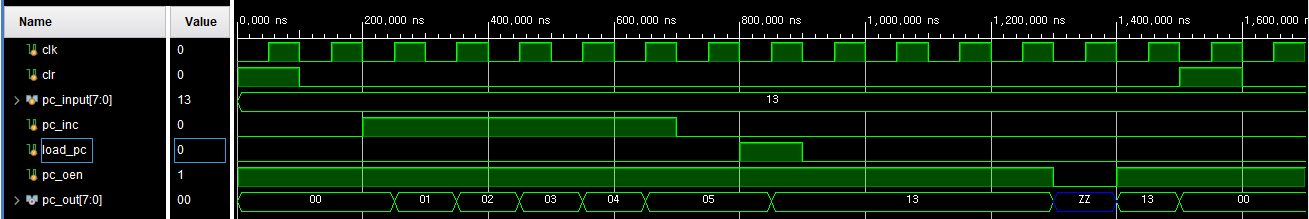
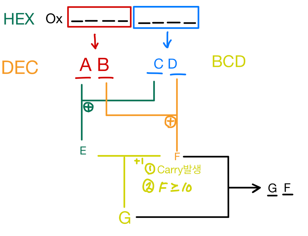
HEX2DEC(Hexa to Decimal)
● 8bit 16진수를 10진수로 변환
● -9 ~ 81 까지의 데이터를 BCD(Binary Coded Decimal)로 표현
● OUTREG(7:4)를 10진수로 변환하여 10자리는 A, 1의 자리는 B에 할당
● OUTREG(3:0)를 BCD 코드로 변환하여 상위는 C, 하위는 D에 할당
● E = A + C, F = B + D
● Carry가 발생하거나 10이 증가하면 E에 +1을하여 G로 저장
● 10의 자리는 G, 1의 자리는 F로 출력.
Full Adder
↓Code & Schematic
fa.v
'timescale 1ns / 1ps

module fa(
    input c_in,
    input x_in,
    input y_in,
    output sum,
    output carry
    );

    assign sum = x_in ^ y_in ^ c_in;
    assign carry = (x_in & y_in) | (x_in & c_in) | (y_in & c_in);
endmodule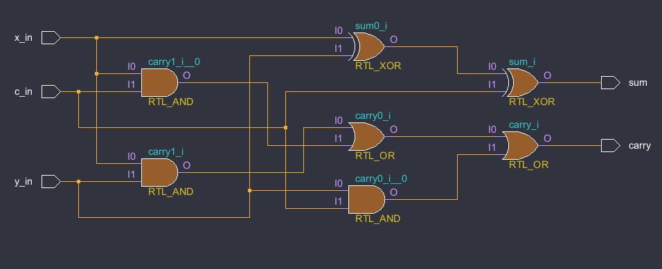
fa4.v
'timescale 1ns / 1ps

module fa4(
    input [3:0] x_in,
    input [3:0] y_in,
    input c_in,
    output [3:0] sum,
    output cout
    );

    wire c1, c2, c3;

    fa fa0(x_in[0], (y_in[0] ^ c_in), c_in, sum[0], c1);
    fa fa1(x_in[1], (y_in[1] ^ c_in), c1, sum[1], c2);
    fa fa2(x_in[2], (y_in[2] ^ c_in), c2, sum[2], c3);
    fa fa3(x_in[3], (y_in[3] ^ c_in), c3, sum[3], cout);
endmodule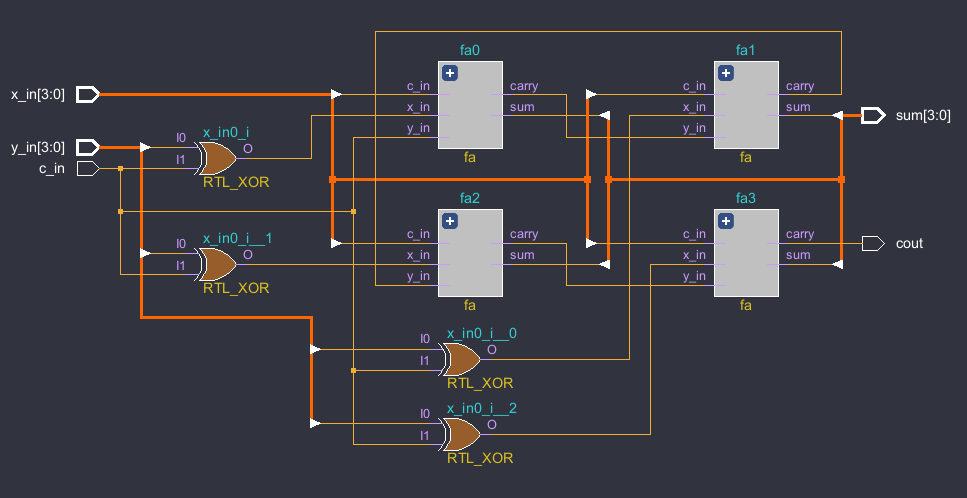
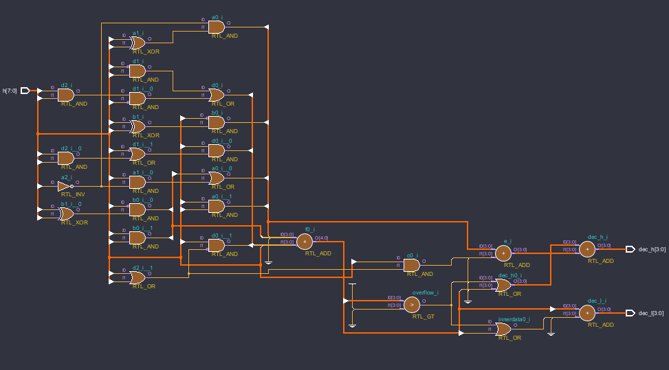
HEX2DEC
↓ Code & Schematic
hex2dec.v
'timescale 1ns / 1ps

module hex2dec(
    input [7:0] h,
    output [3:0] dec_h,
    output [3:0] dec_l
    );

    wire [3:0] a, b, c, d, e, f, innerdata;
    wire cout, overflow;

    assign a[3] = h[6] & h[4];
    assign a[2]=(h[5]&h[4])|(h[6]&~h[4]);
    assign a[1]=(~h[4])&(h[6]^h[5]);
    assign a[0]=(~h[6])&(h[5]^h[4]);

    assign b[3]=h[5]&h[4];
    assign b[2]=(~h[5])&(h[6]^h[4]);
    assign b[1]=(~h[6])&(h[5]^h[4]);
    assign b[0]=0;

    assign c[3:1]=0;
    assign c[0]=h[3]&(h[2]|h[1]);

    assign d[3]=h[3]&~(h[2]|h[1]);
    assign d[2]=h[2]&((~h[3])|(h[3]&h[1]));
    assign d[1]=((~h[3])&h[1])|(h[3]&h[2]&(~h[1]));
    assign d[0]=h[0];

    assign e = a+c;

    assign {cout,f} = b+d;

    assign innerdata = {1'b0,{2{overflow|cout}},1'b0};

    assign overflow = (f>9);

    assign dec_h = (overflow|cout)+e;

    assign dec_l = f+innerdata;
endmodule
tb_hex2dec
'timescale 1ns / 1ps

module tb_hex2dec();

// input
reg [7:0] h;
integer i;

//output
wire [3:0] dec_h;
wire [3:0] dec_l;

//instance
hex2dec uut(
.h  (h),
.dec_h  (dec_h),
.dec_l  (dec_l)
);

initial begin
    h = 0;
    for (i = 0; i < 82; i = i + 1)
        begin
            h = i; #100;
        end
    end
endmodule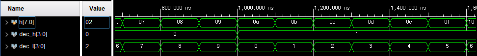
곱셈, 나눗셈 알고리즘
곱셈 알고리즘
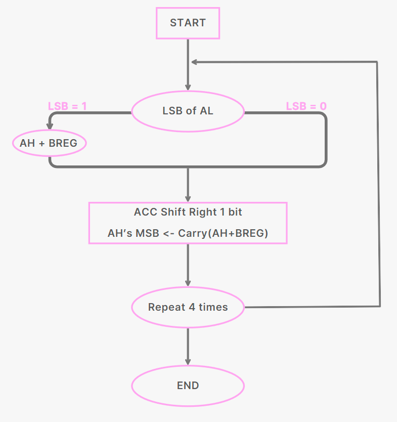
| BREG : 1001 AL : X1001 1001 0000 0000 1001 1010001 |
STEP | AH | AL | ||
| Initial Values | 0000 | 1001 | |||
| 1 => AH = AH + BREG | 1001 | 1001 | |||
| Shift Right ACC | 0100 | 1100 | |||
| 0 => No Operation ( AH = AH) | 0100 | 1100 | |||
| Shift Right ACC | 0010 | 0110 | |||
| 0 => No Operation (AH = AH) | 0010 | 0110 | |||
| Shift Right ACC | 0001 | 0011 | |||
| 1 => AH = AH + BREG | 1010 | 0011 | |||
| Shift Right ACC | 0101 | 0001 | |||
ACC(Accumulator)
구조
● 상위, 하위 4비트로 나누어 사용(AH, AL)
● 내부 버스(8비트)의 상위 4비트에서 AH로 데이터를 받아들임
● AH에서 ALU 연산에 필요한 데이터를 공급받고, 계산 결과를 다시 AH에 저장함
기능
● PASH : AH에서 AL로 4비트의 데이터를 한꺼번에 병렬 이동
● SHR : 1비트 씩 shift right 기능 수행
● SHL : 1비트 씩 shift left 기능 수행
● 내부 버스로 AH, AL의 데이터를 내보냄(AH:4, AL:4)
● ALU 출력을 AH로 받아들임
입력 데이터
● bus_data(4), alu_out(4), carry_in
출력 데이터
● AH(4), AL(4)
mux4to1
↓Code & Schematic
mux4to1.v
'timescale 1ns / 1ps

module mux4to1(
    input [3:0] n,
    input [1:0] s,
    output dout
    );

    reg a;

    always @ (s, n) begin
        case(s)
            2'b00 : a = n[0];
            2'b01 : a = n[1];
            2'b10 : a = n[2];
            2'b11 : a = n[3];
        endcase
    end

    assign dout = a;
endmodule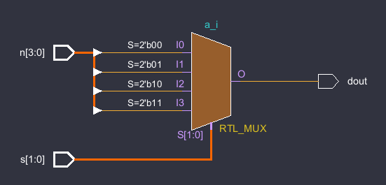
shreg.v
'timescale 1ns / 1ps
module shreg(
    input carry_msb,
    input carry_lsb,
    input clr,
    input clk,
    input [1:0] c,
    input [3:0] data_in,
    output [3:0] data_out
    );

    wire [3:0] a;

    mux4to1 mx0({data_in[3],data_out[2],carry_msb,data_out[3]},c,a[3]);
    mux4to1 mx1({data_in[2],data_out[1],data_out[3],data_out[2]},c,a[2]);
    mux4to1 mx2({data_in[1],data_out[0],data_out[2],data_out[1]},c,a[1]);
    mux4to1 mx3({data_in[0],carry_lsb,data_out[1],data_out[0]},c,a[0]);

    reg4 reg4(data_out,a,1'b1, 1'b1, clk, clr);
endmodule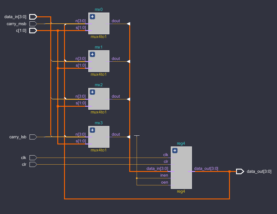
tb_shreg.v
'timescale 1ns / 1ps
module tb_shreg();
//input
reg carry_msb;
reg [1:0] c;
reg [3:0] data_in;
reg clr;
reg clk;
reg carry_lsb;

//output
wire [3:0] data_out;

//instance
shreg uut (
.carry_msb(carry_msb),
.c(c),
.data_in(data_in),
.data_out(data_out),
.clr(clr),
.clk(clk),
.carry_lsb(carry_lsb)
);

// initial input
always #50 clk = ~clk;
initial begin
   carry_msb = 0;
    c=2'b00;
    data_in = 4'b1100;
    clr = 1;
    clk = 0;
    carry_lsb = 0;
    #100; clr = 0;
    #100; c = 2'b11;
    #100; c = 2'b00;
    #100; c = 2'b01;
    #200; c = 2'b00;
    #100; c = 2'b10;
    #200; c = 2'b00;
    #100;
end
endmodule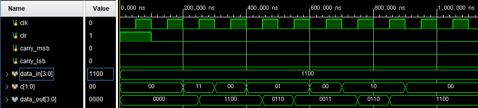
'Circuit Design > 🔥HDL' 카테고리의 다른 글
| [Verilog] Verilog를 이용한 AI 설계 응용 및 SoC 설계 (2) (0) | 2024.09.29 |
|---|---|
| [Verilog] Verilog를 이용한 AI 설계 응용 및 SoC 설계 (1) (0) | 2024.09.25 |
| [Verilog] 27. Counter (0) | 2024.08.23 |
| [Verilog] 26. SPI - AXI Portfolio (2) | 2024.08.23 |
| [Verilog] 25. AXI - SPI Connection Debugging (3) (0) | 2024.08.23 |