
TX
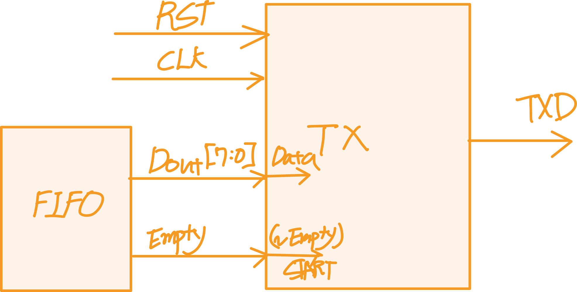
TX Block 부분은 Parallel로 받은 Data를 다시 Serial로 변경시켜서 출력하는 Block입니다.
저번에 제작한 FIFO Block에서 나온 Output을 받아 TX를 제작하겠습니다.
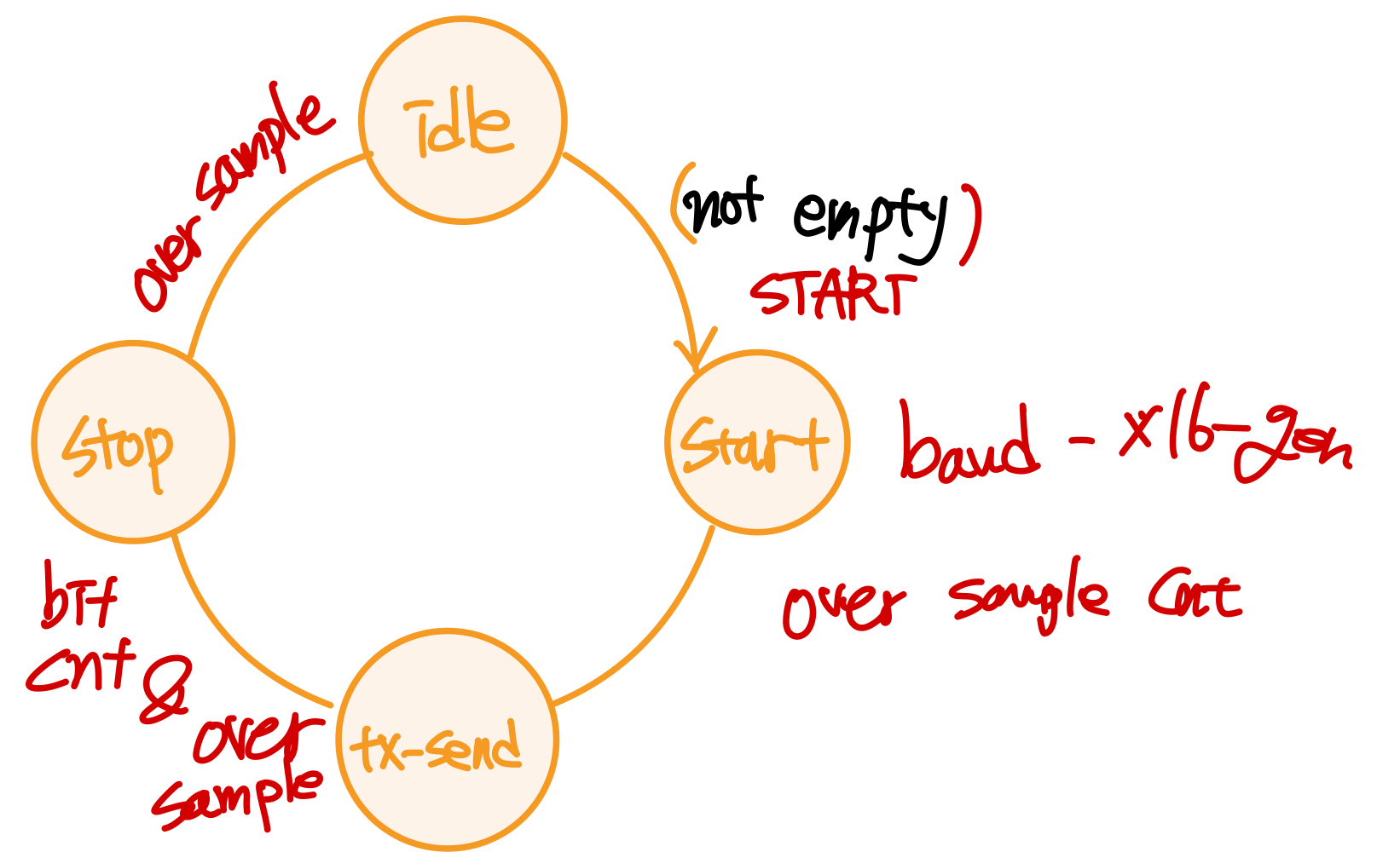
TX에서도 상태 변화를 FSM(Finite State Machine)을 사용하여 구현하겠습니다.
uart_tx.v code
`timescale 1ns / 1ps

module uart_tx(
    input [7:0] DATA,                   // output from the FIFO
    input START,                        //  ~Empty signal from FIFO
    input RST,
    input CLK,
    output reg TXD                          // Serial output. It's equal to RXDin
    );

localparam [1:0] idle = 2'b00,         //FSM state component
                               start = 2'b01,
                               tx_send = 2'b10,
                                stop = 2'b11;
reg [3:0] curr_state, next_state;       //FSM state Register
reg [3:0] over_sample_cnt, bit_cnt;
wire over_sample_cnt_done, bit_cnt_done;
wire parity;
wire baud_x16_en;
reg [7:0] tx_data_in;
wire [8:0] tx_data = {parity, tx_data_in};

always @ (posedge CLK) begin
if(START)
        tx_data_in <= DATA;
end

always @ (posedge CLK) begin  // Check the state per 1 clk, change to the next state
if (RST)
        curr_state <= idle;
else
        curr_state <= next_state;
end

always @ (curr_state, START, over_sample_cnt_done, bit_cnt_done) begin          //FSM
case (curr_state)
        idle :          // when START be a '1' in idle state, Change curr_state to start
                if(START)
                        next_state = start;
                else    // else maintain the idle
                        next_state = idle;
        start :         // when 'over_sample_cnt_done' be a '1' in start state, Change curr_state to tx_send
                if(over_sample_cnt_done)
                        next_state = tx_send;
                else   // else maintain the start
                        next_state = start;
        tx_send :         // when 'over_sample_cnt_done & bit_cnt_done' be a '1' in tx_send state, Change curr_state to stop
                if(over_sample_cnt_done && bit_cnt_done)
                        next_state = stop;
                else   // else maintain the tx_send
                        next_state = tx_send;
        stop :         // when 'over_sample_cnt_done' be a '1' in stop state, Change curr_state to idle
                if(over_sample_cnt_done)
                        next_state = idle;
                else   // else maintain the stop
                        next_state = stop;
        default : next_state = idle;
        endcase
end

// The part of making over_sample_cnt
always @ (posedge CLK) begin
if (curr_state == idle)
        over_sample_cnt <= 5'd15;
else if (baud_x16_en)
        over_sample_cnt <= over_sample_cnt -1;
end
assign over_sample_cnt_done = (over_sample_cnt == 4'd0) & baud_x16_en;

//The part of making bit_cnt
always @ (posedge CLK) begin
if (curr_state != tx_send)
        bit_cnt <= 4'd0;
else if (over_sample_cnt_done)
        bit_cnt <= bit_cnt + 1;
end
assign bit_cnt_done = over_sample_cnt_done & (bit_cnt == 4'd8);

//make a parity
assign parity = tx_data[7:0];

//Parallel to Serial (TXD)
always @ (curr_state, bit_cnt) begin
        if (curr_state == idle || curr_state == stop)
                TXD = 1'b1;
        else if (curr_state == start)
                TXD = 1'b0;
        else
                TXD = tx_data[bit_cnt];
end

//instance the uart_baud_gen
uart_baud_gen baud_gen_10 (
        .RST    (RST),
        .CLK    (CLK),
        .BAUD_X16_EN    (baud_x16_en)
);

endmodule
uart_top.v code
`timescale 1ns / 1ps

module uart_top(
    input RST,
    input CLK,
    input RXD,
    output [6:0] AN,
    output CA,
    output PAR_ERR,
    output FRM_ERR,
    output TXD
    );

wire    [7:0]   rx_data;
wire rx_data_rdy, empty;
wire    [7:0] dout;
reg     [7:0] dout_reg;

always @ (posedge CLK) begin
        if (~empty)
        dout_reg <= dout;
        end

uart_rx uart_rx_0 (
    .RST        (RST),
    .CLK        (CLK),
    .RXD        (RXD),
    .RX_DATA    (rx_data),
    .RX_DATA_RDY    (rx_data_rdy),
    .FRM_ERR    (FRM_ERR),
    .PARITY_ERR (PAR_ERR)
    );

my_fifo fifo_0(
    .RST        (RST),
    .CLK        (CLK),
    .DIN        (rx_data),
    .WR_EN      (rx_data_rdy),
    .FULL       (FULL),
    .DOUT       (dout),
    .RD_EN      (~empty),
    .EMPTY      (empty)
    );

display_inf disp_0 (
    .RST            (RST),
    .CLK            (CLK),      // 125 Mhz
    .NUM_1S         (dout_reg [3:0]),
    .NUM_10S        (dout_reg [7:4]),
    .CA             (CA),
    .AN             (AN)
    );

uart_tx uart_tx_0 (
        .RST    (RST),
        .CLK    (CLK),
        .START  (~empty),
        .DATA    (dout),
        .TXD    (TXD)
);


endmodule
가장 아래에 tx부분을 추가하여 module들을 연결해 주었습니다.
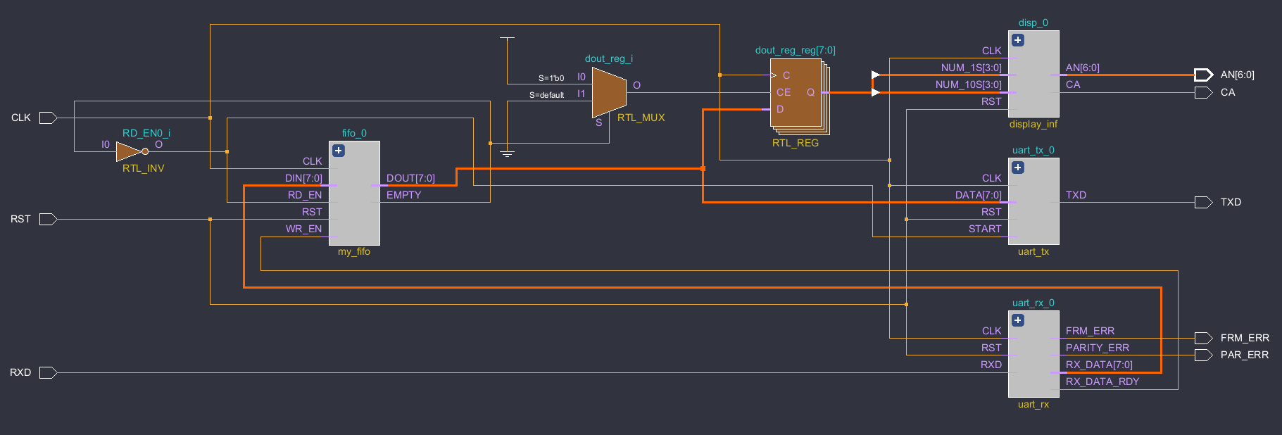
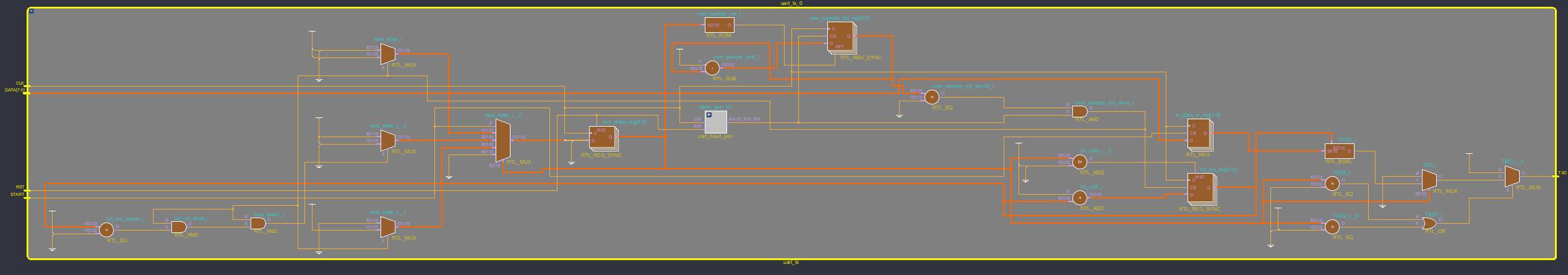
이렇게 FIFO와 Baud_x16_gen 모듈의 값에 따른 FSM을 구현한 TX module을 제작하여, 기존 uart에 연결하는 과정까지 마무리하였습니다
'Circuit Design > 🔥HDL' 카테고리의 다른 글
| [Vitis] 0. Preview(Hello World) (0) | 2024.06.24 |
|---|---|
| [Verilog] Vivado Setting [Dark Theme(Vivado 다크모드)] (0) | 2024.06.10 |
| [Verilog] 11. UART(2) (0) | 2024.06.03 |
| [Verilog] 10. FIFO(First In First Out) (0) | 2024.06.03 |
| [Verilog] 9. RAM(Random Access Memory) (0) | 2024.05.27 |